


PCB Resistors and Board Design
PCB resistors are designed to be mounted and soldered to printed circuit boards; they control current flow and divide voltages, among other things. PCB resistors come in many shapes and sizes, but they’re all designed to fit easily into board layouts. They have two terminals that can be soldered to the conductive traces on the PCB so they can be connected electrically to the rest of the circuit.
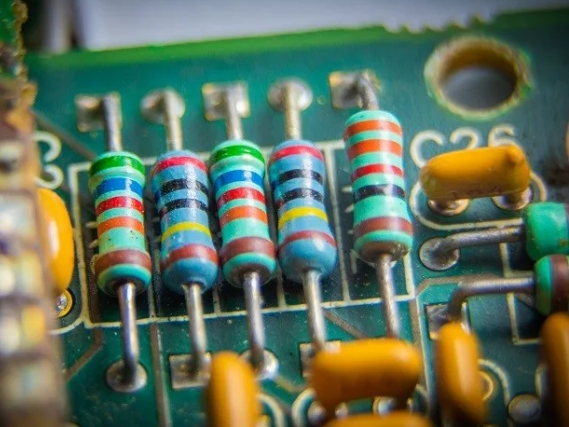
One type of PCB resistor, called a through-hole resistor, has wire leads that pass through holes on the PCB and are soldered to copper traces on both sides. Another type, a surface-mount resistor, is soldered to the board’s pads directly on the board’s surface. These and other types of PCB resistors are detailed in the chart below.
| Types of PCB Resistors | |
| Through-Hole Resistors | Axial resistors: leads on both endsRadial resistors: leads emerging from the same sideDual in-line package (DIP) resistor networks: multiple resistors in a single package, often used for IC configurations |
| Surface Mount Device (SMD) Resistors | Chip resistors: small rectangular resistors soldered directly onto the surface of the PCB Thin film resistors: low-noise resistors with a thin film of resistive material used for temperature stability and toleranceThick film resistors: thick resistive layer, less precise but cheaper than thin film resistorsNetwork resistors: SMD resistor networks are similar to DIP networks but designed for surface mounting |
| Variable Resistors | Potentiometers: adjustable resistors with a variable wiper often used for volume controls and setting specific circuit parametersTrimmer resistors: small potentiometers designed for fine-tuning circuit parameters during manufacturing or calibration |
| High-Power Resistors | Wirewound resistors: made by winding a resistance wire around an insulating core; suitable for high-power applicationsPower film resistors: can handle high power levels and dissipate heat effectively |
| Fusible Resistors | Fusible resistors: designed to act as fuses when subjected to excessive current, offering protection to the circuit. |
| High-Frequency Resistors | Precision RF resistors: designed for high-frequency applications; low parasitic capacitance and inductanceMicrowave resistors: designed for microwave and RF applications |
Resistance, power rating, and tolerance all play a role in selecting PCB resistors. Electronic devices employ resistors to control voltage and current.
The Role of PCB Resistors in Board Design
Resistors are crucial to PCB design and functionality. They control current flow, divide voltage, and set specific circuit parameters. Here are some design considerations when using PCB resistors.
PCB Layout and Placement
PCB resistor placement and layout are crucial. To avoid parasitic effects, it’s important to space, orient, and connect resistors correctly.
Resistance Value
PCB design starts with choosing the resistor’s resistance value. It helps set voltage levels and decides how much current will flow through a particular part of the circuit. It’s essential to choose the correct resistance value for your circuit.
Tolerance and Precision
A resistor’s tolerance — how closely the actual resistance matches the specified value — is crucial in high-precision applications. Circuit operation depends on choosing resistors with the correct tolerance.
Voltage Dividers
Voltage divider circuits commonly use PCB resistors, which divide input voltage to make a specific voltage output. This comes in handy for things like sensor interfacing and setting reference voltages.
Biasing and Operating Points
A resistor is often used to set the operating point (biasing) in amplifiers and transistors. For amplifiers to work efficiently and linearly, they need proper biasing.
Signal Conditioning
PCB resistors are used in many applications, like filtering, amplifying, or attenuating signals. In analog electronics, resistors and capacitors are often used to create different filter responses.
Current Limiting
Using PCB resistors, you can limit the current flowing through specific parts of the circuit to prevent damage to components.
Temperature Compensation
PCB resistors can be used for temperature compensation. You can use their resistance to offset other components’ temperature-dependent characteristics in the circuit.
Matching and Balancing
To ensure accuracy and stability, resistors are used for matching and balancing in precision circuits like operational amplifiers and analog-to-digital converters.
Current Shunting and Sensing
Power electronics and measurement applications use shunt resistors to measure current flow. They’re often used with precision operational amplifiers because of their low resistance.
Impedance Matching
RF and microwave circuits use resistors for impedance matching to transfer power between components efficiently.
Power Dissipation
It’s vital to choose resistors with the right power rating. PCB resistors can generate heat in high-power applications, so proper heat sinking is needed to prevent overheating and damage to components.
Engineers have to take all these factors into account when designing PCBs. Choosing PCB resistors based on their temperature coefficient, package size, and reliability is essential for long-term performance.