


How to Solder Electronic Components
Basic soldering guide on how to solder electronic components to a printed circuit board (PCB). This is a detailed and complete soldering guide for both automated soldering in mass production and manual soldering in PCB rework and repair.
How to Solder Electronic Components – Introduction
Soldering is basically a technique of joining two metals using a third metal or alloy.
Proper soldering technique and solder quality are the lifeline of any solder joint and PCB assembly. Solder quality and soldering technique determine the life and performance of any electronic device, appliance or gadget.
In electronic PCB manufacturing, assembly and rework, the metals to be joined are the leads of electronic components (through-hole or SMD) to the copper tracks on the PCB. The alloy used to join these two metals is solder, which is basically either tin-lead (Sn-Pb) or tin-silver-copper (Sn-Ag-Cu). Tin-lead solder is called leaded solder because it contains lead, while tin-silver-copper solder is called lead-free solder because it does not contain lead.
Solder is melted using a wave soldering machine, reflow oven or a regular soldering iron and then the melted solder is used to solder the wires or electronic components to the PCB or printed circuit board. After the electronic components are assembled, the circuit board is called PCB assembly or PCBA (Printed Circuit Board Assembly)
Some other terms like soldering and welding are also often associated with soldering. But remember that soldering, brazing and welding are different from each other. Soldering is done using solder while brazing is done using a filler metal with a lower melting point. In welding, the base metal also melts while joining the two metals which is not the case with soldering and brazing.
Soldering Materials
Let us first discuss in detail all the basic soldering materials and consumables required.
- Flux
Flux plays a vital role in any soldering process and electronic PCB manufacturing and assembly. Flux removes any oxides and prevents oxidation of metals which helps in improving the quality of soldering. In the electronic PCB assembly process, flux removes any oxides and impurities from the copper tracks on the PCB and oxides on the leads of electronic components. These oxides are the biggest resistance to a good solder joint and flux plays a very important role here by removing these oxides.
There are basically three types of fluxes used in soldering:
- R-type fluxes – These fluxes are inactive and are used where there is least oxidation.
- RMA-type fluxes – These are rosin lightly activated fluxes. These fluxes are more active than R-type fluxes and are used where there is more oxidation.
- RA-type fluxes – These are rosin activated fluxes. These fluxes are very highly active and are used where there is excessive oxidation.
- Solder (Wire, Solder Bar, Solder Paste, Solder Balls, Solder Preforms)
Solder is the lifeline of any PCB assembly. The quality of solder used during soldering and PCB assembly determines the life and performance of any electronic machine, device, appliance, mobile phone or gadget.
There are various solders of different alloys but the true alloy is the eutectic solder. The melting point of eutectic solder is exactly 183 degrees Celsius (Sn/Pb). An alloy with a ratio of 63/37 between tin and lead is a eutectic solder, so 63/37 tin-lead solder is called eutectic solder.
Non-eutectic solders do not change from solid to liquid at 183 degrees Celsius. They may remain semi-solid at this temperature. The alloy that is closest to eutectic solder is tin-lead alloy, which has a ratio of 60/40. For many years, the favorite solder of electronic manufacturers has been 63/37. It is still widely used all over the world.
Because lead is harmful to the environment and humans, the European Union implemented RoHS (Restriction of Hazardous Substances) and took the initiative to ban the use of lead and other hazardous substances in electronic products. The European Union has decided to remove lead from solder and electronic components. Therefore, more and more electronic companies in the world are moving to RoHS. This has led to the emergence of another type of solder, lead-free solder.
This solder is called lead-free solder because it does not contain lead. Lead-free solder alloys have a melting point of about 250°C (482°F), depending on their composition. The most common lead-free alloy is tin/silver/copper in the ratio Sn96.5/Ag3.0/Cu0.5 (SAC). Lead-free solder is also known as “lead-free” solder.
Solder Forms:
Solder comes in many forms:
Solder wire
Solder bar
Solder preform
Solder paste
BGA solder balls
- Electronic components
Electronic components are of two types: active and passive.
Active components are those that have gain or directionality. For example transistors, integrated circuits or ICs, logic gates.
Passive electronic components are those that do not have gain or directionality. They are also called electrical components or electrical assemblies. For example resistors, capacitors, diodes, inductors.
Again, electronic components can be through-hole or SMD (surface mount devices or chips).
Soldering tools and equipment
As mentioned above, soldering can be done in 3 ways:
- Wave soldering: Wave soldering is suitable for mass production. The equipment and raw materials required for wave soldering include: wave soldering machine, solder bar, flux, reflow checker, dip soldering tester, spray fluxer, flux controller.
- Reflow soldering: Reflow soldering is suitable for mass production and is used for SMD soldering. The equipment and raw materials required for reflow soldering include: reflow oven, reflow checker, stencil printer, solder paste, flux.
- Manual soldering: Manual soldering is suitable for small-scale production and PCB repair and rework. The equipment and raw materials required for manual soldering include: soldering iron, soldering station, solder wire, solder paste, flux, desoldering iron or desoldering station, tweezers, solder pot, hot air system, wrist strap, fume absorber, static eliminator, heat gun, pick-up tool, lead former, cutting tool, microscope and magnifying lamp, solder ball, flux pen, desoldering tape or desoldering wire, desoldering pump or desoldering spoon, overcoat pen, antistatic material, etc.
- BGA Soldering: Another electronic component is BGA or ball grid array. They are special components and require special soldering. They do not have any leads, but use solder balls under the components. Since the solder balls must be placed under the components and soldered, the soldering of BGA becomes a very difficult task. BGA soldering requires BGA soldering and rework system and solder balls.
Wave Soldering Process
There are many types of wave soldering machines, suitable for leaded wave soldering and lead-free wave soldering, but they all have the same mechanism. There are three zones in any wave soldering machine –
Preheating Zone: This zone preheats the PCB before soldering.
Flux Zone: This zone sprays the flux onto the PCB.
Soldering Zone: The most important zone where the molten solder is present.
There can also be a fourth zone called the cleaning zone where the flux is cleaned after soldering is complete.
Wave Soldering Process
A conveyor belt is constantly moving around the factory. Employees insert electronic components into the PCB that is constantly moving forward on the conveyor belt. Once all the components are in place, the PCB moves through different zones to the wave soldering machine. The solder wave in the solder tank solders the components and the PCB moves out of the machine where it is cleaned and tested to see if there are any defects. If there are any defects, some rework/repair work needs to be done by hand soldering.
Reflow Soldering Process
Reflow soldering uses SMT (Surface Mount Technology) to solder SMDs (Surface Mount Devices) onto the PCB. Reflow soldering is divided into four stages –
- Preheating
- Hot soaking
- Reflow;
- Cooling.
During this process, solder paste is printed on the tracks on the circuit board where the components are to be soldered. The printing of solder paste can be done using a solder paste dispenser or a stencil printer. The circuit board with solder paste and solder paste components is then passed through a reflow oven where the components are soldered to the circuit board. The circuit board is then tested for any defects and if there are any, rework and repair are done using a hot air system.
Manual Soldering Process
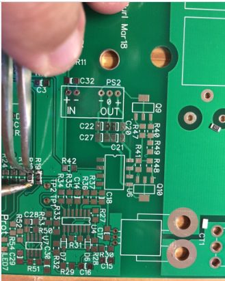
Manual soldering is mainly used for small-scale production or repair and rework. Manual soldering of through-hole components is done using a soldering iron or soldering station.
Manual soldering of SMD components is done using a hot air pen or a hot air rework blower. Manual soldering of through-hole components is easier compared to SMD soldering.
Basic Soldering Guidelines: Precautions
Always keep a thin layer of solder on the tip of the soldering iron.
Use flux that is as mild as possible but still provides a strong solder joint.
Keep the temperature as low as possible while maintaining enough temperature to solder the joint quickly (2 to 3 seconds maximum for electronics soldering).
Match tip size to the job.
For maximum efficiency, use the shortest tip possible.
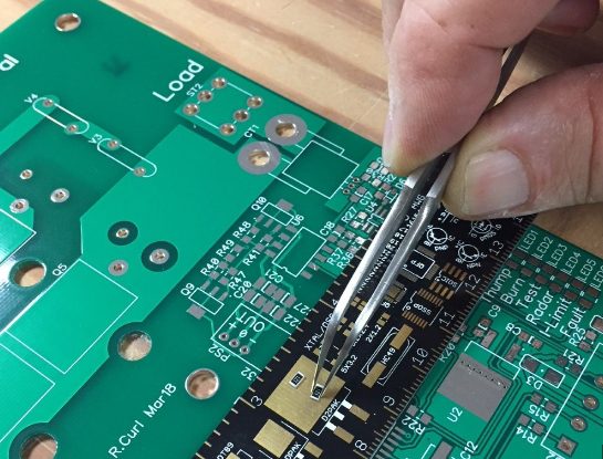
SMD Hand Soldering Process
Method 1 – Pin-by-Pin Method Used for: 2-pin SMD components (0805 capacitors and resistors), pitch >= 0.0315″ in small outline packages, (T)QFP, and SOT (Mini 3P).
Method 2 – Immersion and suction method Used for: Small outline packages and (T)QFP with pitch <= 0.0315″
Method 3 – Solder paste method Used for: BGA, MLF/MLA packages; where the pins are under the part and cannot be touched.