Flexible application of high frequency plate design method
High-frequency boards are the basis for the realization of microstrip circuit engineering. In the process of microstrip circuit design, sometimes the original design boards are out of stock, or it is necessary to use more reliable high-frequency boards for circuit design. So how to solve the above problems simply, quickly and accurately based on the original design? The author shares a practical design method with you through an engineering example.
Introduction to Design Methodology
The original design was a microstrip coupled filter implemented using RO3010:

Figure 1: Microstrip coupled filter layout
Frequency response of microstrip circuit: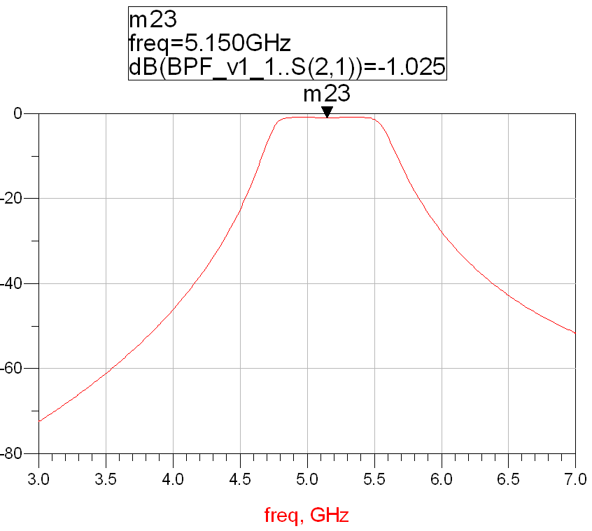
Figure 2: Frequency response of a circuit designed using RO3010
Circuit structure of microstrip coupled filter: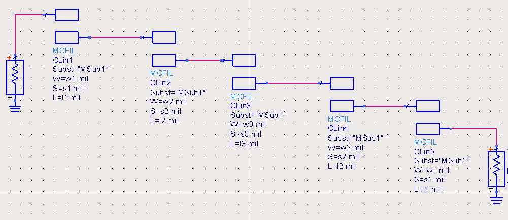
Figure 3: Circuit structure of microstrip coupled filter
The performance of the microstrip coupled filter is affected by the line width w of the parallel coupled line, the coupling line spacing s and the coupling line length l. In the circuit structure of Figure 3 above, there are three different sets of parameters: w1, s1, l1, w2, s2, l2 and w3, s3, l3. When using the high-frequency board RO3010 to design the circuit, the values of these three sets of parameters are shown in Table 1:

Table 1: Physical dimensions of the circuit of high-frequency board RO3010
When designing the principle of microstrip coupled filter, its electrical performance remains unchanged, but when using high-frequency board to implement the design project, the calculated physical size is different due to the different index parameters of the board. The following table shows the main technical parameters of RO3010:

Table 2: Main parameters of high frequency plate RO3010
Use the coupled line parameter calculation function in the simulation software to convert the parameters, input the plate index parameters and the physical dimensions of the circuit structure into the conversion interface for calculation, and use the physical dimensions of the circuit to parse the electrical parameters:

Figure 4: Parameter conversion interface
By inputting the main parameter indicators of the high-frequency board RO3010, the physical dimensions of the circuit, and the operating frequency into the parameter conversion interface, the electrical parameters of the circuit can be analyzed. The ZE, Z0, C_DB, etc. under the Electrical tab in Figure 4 are the electrical parameters.
Looking for mainstream high-frequency boards, KKPCB’ RT/duriod 5880 has stable electrical performance and can effectively improve the reliability of the circuit. At the same time, this board is widely used and can be quickly retrieved from stock. According to KKPCB’ agent Shiqiang Company, this board is rarely out of stock. Therefore, when choosing this board for circuit design, there is no need to worry about supply issues. The following table shows the main technical parameters of RT/duriod 5880:

Table 3: Main parameters of high-frequency plate RT/duriod5880
Keep the electrical parameters unchanged, input the parameter indicators in Table 3, and synthesize the physical dimensions of the circuit. The resulting physical dimensions of the circuit are shown in Table 4:

Table 4: Physical dimensions of circuits for high-frequency board material RT/duriod 5880
Bringing the new circuit structure size and high-frequency board RT/duriod 5880 index into the design, we get the frequency response of the circuit:
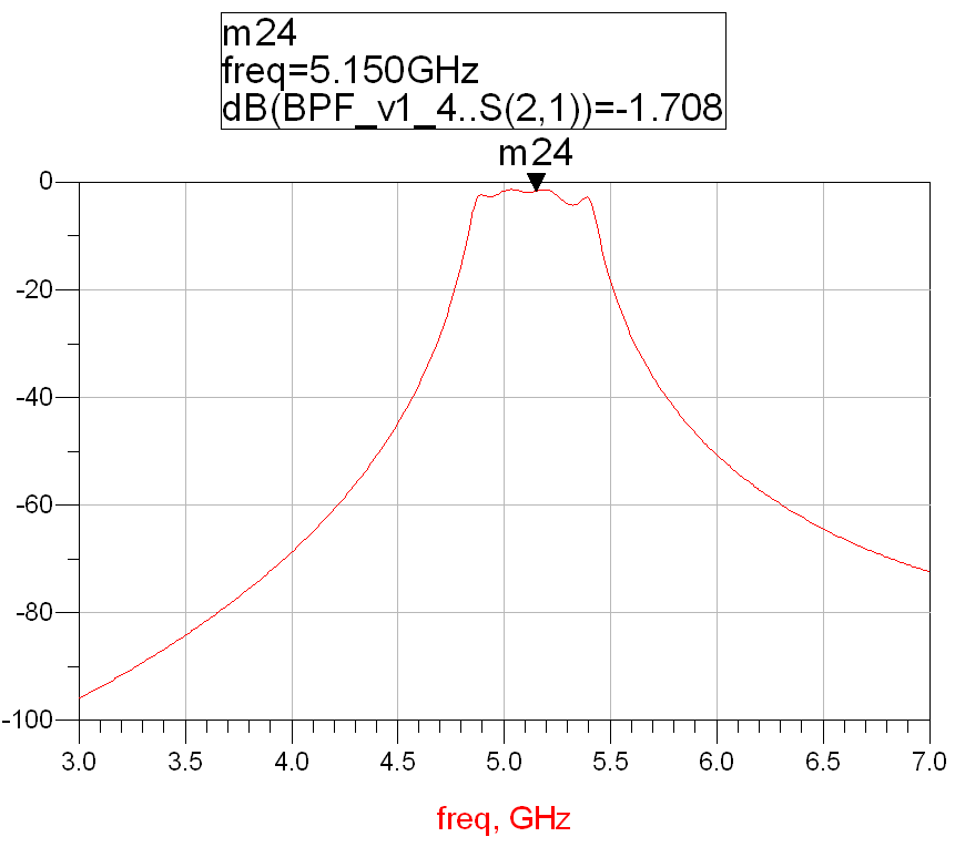
Figure 5: Frequency response of a circuit designed using RT/duriod 5880
Comparing Figure 2 and Figure 5, the frequency response of the circuit designed using two high-frequency plates has not changed much, but the filter’s insertion loss , in-band unevenness, and bandwidth have deteriorated a bit, and parameter optimization design is needed. At the same time, the coupling width s1=4.8mil=0.12mm in Table 4 exceeds the actual processing accuracy of the microstrip line, which will cause difficulties in manufacturing and ultimately affect the platemaking performance. Without special treatment, the minimum value of the microstrip line processing accuracy is guaranteed to be 0.2mm, and the s1 value is adjusted to 10mil.
Optimize the circuit parameters so that the frequency response of the circuit meets the index requirements before the change. The frequency response of the circuit after optimization is:
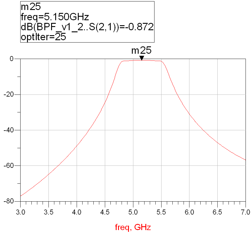
Figure 6: Frequency response of the circuit optimized using RT/duriod 5880
The physical dimensions of the optimized circuit are shown in Table 5:

Table 5: Circuit physical size optimization values of high-frequency board RT/duriod 5880
Comparison of frequency responses of circuits designed using two types of boards:
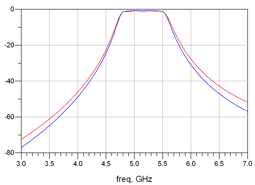
Figure 7: Frequency response comparison of two board design PCB circuits
The red and blue curves in Figure 7 represent the frequency responses of circuits designed using RO3010 and RT/duriod 5880 high-frequency boards, respectively. The performance indicators of both meet the requirements.
The above is some of the design experience I have accumulated in the application of KKPCB high-frequency board engineering. I have summarized it and shared it with you, hoping it will be helpful to you.


